CNC Drawing Arm
Written January 2022
Introduction
When I arrived home for winter break after my first semester of university in 2017, my world had been turned on its side. I had finally recieved formal programming education.
I don’t remember what the inspiration was. I honestly think it might have just been the math high I got after finishing Calculus 3, which includes cylindrical and spherical 2nd order integrals - just taking the volume defined by a function defined in those coordinates. I was suddenly much more familiar with the polar system, and knew the kinematics of an arm like this would be possible for me to write.
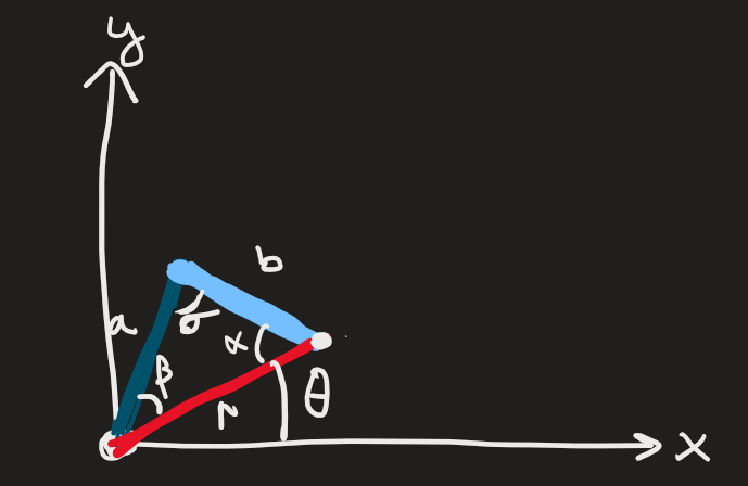
A triangle rotated about the origin is the base concept for this arm. Given a radius, use the law of cosines to solve for omega. Then, use the knowledge of b to solve for beta. The angle of the ‘shoulder’ is theta + beta and the angle of the elbow is omega.
Version 1 (December 2017)
The initial concept was made in several hours of a late night on Monday, December 18th 2017. It was likely that a few days prior I started on the math and some rough code, but I didn’t start building until that night. I only used supplies I had on-hand, servo motors that came in my arduino starter kit and some balsa rods.
Frist came testing the physical apparatus - setting the position of the servos to the values read from two potentiometers. You may recognize this as one of the servo example scripts.
void loop() {
  val1 = analogRead(potpin1);
  val1 = map(val1, 0, 1023, 0, 180);
  val2 = analogRead(potpin2);
  val2 = map(val2, 0, 1023, 0, 180);
  myservo1.write(val1);
  myservo2.write(val2);
  delay(15);
}
The wild flailing is due to a bad connection to the shoulder potentiometer. I think a jumper is attached to one of the legs with scotch tape. To be fair, I just wanted to make sure it worked.
Next was to get it controlled with commands from an input, I just took angle values in degrees over serial. Keep it simple.
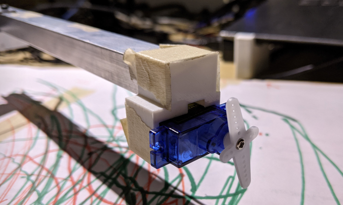
After that, I needed to add a Z-axis. I placed the servo that controlled the pen angle to the pivot point, and routed a string around to a hinge made of tape and guided by paper. Lightweight and fast would be the solution here.
This raised the issue that would ultimately doom this project, but I naiively hoped I could leave it behind when i moved away from balsa. The torque at the end of the arm is rather high, and changes as the radius changes. I ended up adding a small post that dragged on the paper to keep the end at a consistent height.
By this point I was making sure that the calculations I were doing were correct, that I was getting a consistent radius and theta from the origin, even as the arm changed angles. The biggest problem here was related to the dragging post - approaching a point from above or below resulted in two separate ending positions, due to flex in the arm and slack in the servos (only accurate to one degree).
From here I just put a rectangular to polar conversion, and the code worked well enough to process X-Y pairs and plot lines between them.
// rectangular to polar (radians)
rad = sqrt(yval*yval + xval*xval);
thet = asin( yval / rad ) * (180 / pi);

// convert radius to angles of the triangle
omega = acos((armA*armA + armB*armB - rad*rad) / ( 2 * armA * armB ));
beta = asin(( armA * sin(omega) ) / rad );

// convert to degrees
beta = beta * (180 / pi);
omega = omega * (180 / pi);

// add the triangle to the base theta
thet = thet + beta + 10;
// adjust for the zero location of the second servo
omega = omega - 45;
From here, the next step would be better hardware. I put the project aside.
Version 2 (June 2018)
I learned what stepper motor drivers are, redesigned the schematic in Fritzing (lost those files) and made an order from AliExpress. Ordering with the cheapest shipping had about a 40 day shipping time, and by the time they arrived I was busy with other things.
Version 3 (December 2018)
I finally took the opportunity to write the next version of the software that utilized the stepper motors. I also now knew how to use functions in C, which I hadn’t known in 2017. Heres a function to drive a stepper to a specific angle, while having a limit switch that can interrupt the movement if necessary.
void stepper_angle(int motor, int deg) {
  // motor 1 or 2
  // dir = 1 for ccw, -1 for cw
  // deg = degrees
  int dir_pin;
  int step_pin;
  int lim_pin;
  int dir;
  int current_deg = 0;

  // Figure out what motor we are talking about
  if ( motor == 1 ) {
    dir_pin = s1_dir_pin;
    step_pin = s1_step_pin;
    lim_pin = lim1_pin;
  }
  else if ( motor == 2 ){
    dir_pin = s2_dir_pin;
    step_pin = s2_step_pin;
    lim_pin = lim2_pin;
  }
  else {
  }

  // Figure out what direction we are going
  if (deg > 0) {
    digitalWrite(dir_pin,HIGH);
  }
  else if (deg < 0) {
    digitalWrite(dir_pin,LOW);
    deg *= -1;
  }
  else {
  }

  // Move that far!!
  while (current_deg < deg) {
    digitalWrite(step_pin,HIGH);
    delayMicroseconds(stepper_delay);
    digitalWrite(step_pin,LOW);
    delayMicroseconds(stepper_delay);
    current_deg += deg_per_step;
    if ( digitalRead(lim_pin) == HIGH ) {
      break;
    }
    else {

    }
  }
}
I didn’t actually got the stepper motors working that winter, I wasn’t pulling certain pins on the drivers high or low or something, and without getting the motors rotating at all I was pretty discouraged and put them back on the shelf.
Version 4 (August 2020/March 2021)
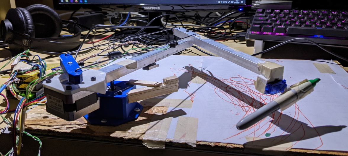
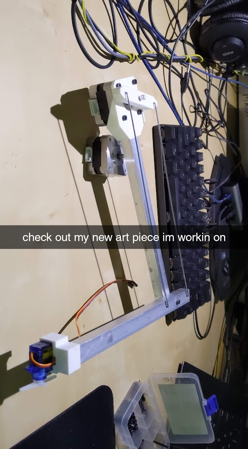
On August 3rd, 2020, I was discouraged enough after crashing my drone into a lake that I decided to finally give another crack at the drawing arm I had been putting off. I don’t think I was in the mood to do some programming, so I just opened solidworks, grabbed some scrap aluminum channel I had used for my original lightbars project and finally built a robust mechanical version. The metal rods for the elbow are construction marking flags, burning through that pack of 100 I bought.
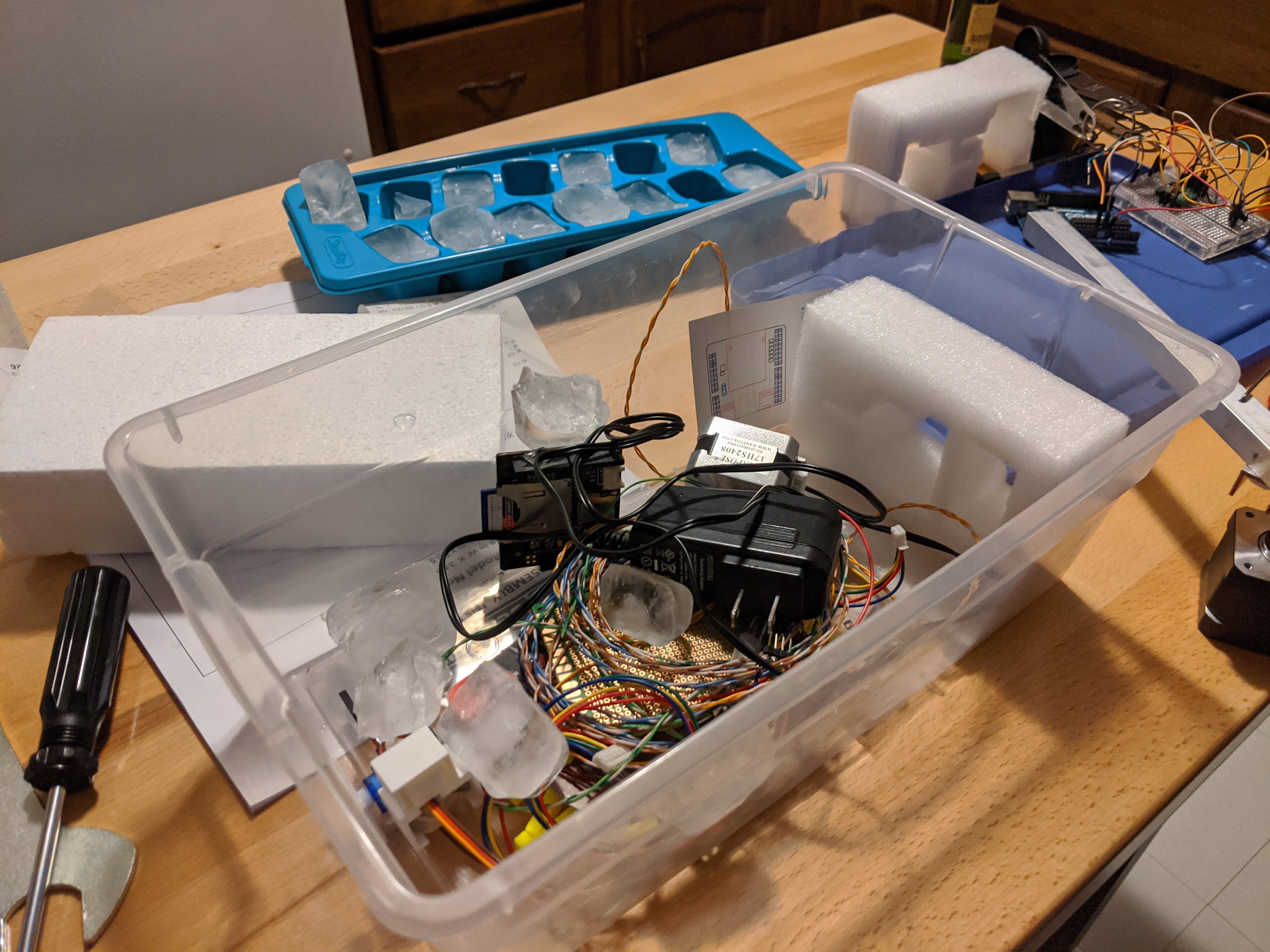
I also breadboarded and got the actual motors working, but I don’t have any media of that. I just have this picture from Thursday August 27th at 1:27 in the morning, in the middle of an apartment party. I don’t remember what was going on, but theres ice in the bin. No components were harmed.
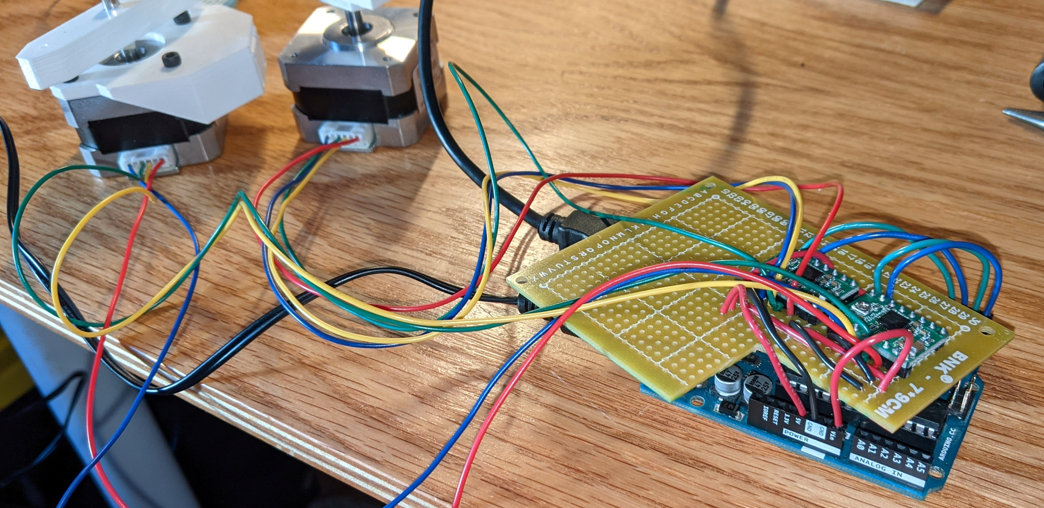
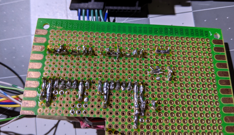
The semester started, I forgot about the device. On Saturday March 13th, 2021, I pulled the falling-apart breadboard out of the bin and soldered everything onto a protoboard. Simple and functional. Don’t flame me.
Then I printed a mount to secure the shoulder servo to a piece of wood, some bumpers for the limit switches, and thats it for the fourth and final version.
I wrote a bare minimum GCODE parsing section on the arduino, and got the SD card SHIELD plugged in. The two modes of operation are by saving a file on the SD card and it runs automatically on startup, or by sending GCODE over serial manually or using a 6-line python script.
There are hundreds of unique GCODE commands for everything anyone has wanted to do on a CNC machine. I was going to write more of the cases, but Cura slicer breaks all curves into very small straight line segments. There would be no reason to use the arcs, which would be hard to do anyway. I home the arm before starting to read the file, so additional homing actions would be redundant. Pretty much all of the file gets ignored except for the important parts.
void interpret(char gline[]) {
  arm_moving = true;
  switch (gline[0]) {
    case 'G':
      switch (gline[1]) {
        case '0':
        case '1': // parse the x,y, and z
                  line(parseNumber(gline, 'X'), parseNumber(gline, 'Y'), parseNumber(gline, 'Z'));
                  Serial.println("completed");
                  break;
        default: return;
      }
  }
  arm_moving = false;
}
Here is the serial log from the above movement. Not shown is the movement from HOME to (150,100).
Beginning setup
could not open sd. Entering serial input mode.
Startup done
recieved: G1 X150 Y100
completed
recieved: G1 X150 Y200
completed
recieved: G1 X200 Y200
completed
recieved: G1 X200 Y000
completed
recieved: G1 X300 Y000
completed
recieved: G1 X300 Y100
completed
recieved: G1 X300 Y200
completed
One problem that arises is ‘drawing straight lines’. This is solved on rectangular machines by a neat velocity calculation, but is a bit more complex on arms. I thought about calculating a set of intermediate points along the line that are indefinitely close to each other - classic calculus approach. However, I realized my angular precision was still not very high. I set the drivers to 16th step mode on my 200 step motor - 0.1125 deg/step - but the motors didn’t actually have that kind of precision. Additionally, Cura already breaks lines into very short line segments, possibly to improve print time remaining estimates (number of lines in the file ~= time left in the print?). It wasn’t worthwhile to pursue.
That problem that I mentioned earlier, about the end of the arm flexing and dragging? Still here. There just isn’t enough rigidity on the arm to smoothly move the sharpie. Getting that perfect Z-height is also pretty difficult, because to keep the weight down i just masking-taped the sharpie to the servo arm.
Second problem is how hot the stepper motors get. The drivers I bought are the cheapest ones availible, so the current tuning is just enough to keep the motors from shaking. Without a metal frame acting as a heat sink, the motors themselves get hot enough to melt the PLA parts they are attached to if I run it for too long. That makes the arm movement sloppier. Its just not a very good design.
As a fun use case for no reason, I actually integrated it with a discord bot. As a novelty telepresence, I removed the whole arm and attacehed a camera to the shoulder motor. I added a bot command that read /pan ANGLE and sent it as an X-Y position to the arm over serial. This just moved the camera side to side, so people on video call could pan the camera. It was…functional. I don’t have any media of it working, as I used it at my hectic graduation party and then never again.

All in all, this was a fun novelty and good learning experience. It followed my knowledge in software and hardware through university, culminating with using it at my graduation party. It just shows how long one person can drag out a mildly interesting project, if they are determined. I might use the parts to make a rectangular plotter thats actually good, like this one. To anyone looking for the source code or STL files to build your own, don’t. Build something else.
Until next time.